
33kV SF6 Insulated Load Break Switch: Technical Analysis of Gas-Insulated Pole-Mounted Switching
Selecting a 33kV load break switch for a pole-mounted distribution network without understanding its internal SF6 insulation and switching physics often leads to premature gas leakage, unreliable fault isolation, and unsafe field operation.
In this article
- What Is a 33kV SF6 Insulated Load Break Switch
- Core Technical Advantages of the SF6 Gas-Insulated Design
- Typical Applications and Service Boundaries
- Comparison: SF6 vs Vacuum vs Air-Insulated Load Break Switches
- Summary
Distribution utilities across Asia, the Middle East, Africa and Latin America are rapidly expanding 33kV (36/40.5kV class) overhead networks. The pole-mounted load break switch (LBS) is the workhorse that lets crews de-energize a feeder section, isolate a faulted span, and restore power by loop switching — all without a crew climbing into a live bay. This article breaks down how the GuoYuan PGS-40.5 (model FLW-12/24/40.5) SF6-insulated load break switch is built and why its design choices matter for reliable field service.
1. What Is a 33kV SF6 Insulated Load Break Switch
A 33kV SF6 insulated load break switch is a three-phase, pole-mounted disconnect-class device that makes and breaks load current, overload current, and charging current on a medium-voltage distribution feeder. It is not a circuit breaker: it is not rated to interrupt full short-circuit fault current. Its job is to safely open and close the circuit under normal load conditions and to visibly isolate a section so downstream work can proceed.
In the PGS-40.5 design, the main contacts, arc-quenching path and insulating gas are sealed inside a gas-insulated (GIS) enclosure filled with SF6 at a rated operating pressure of 0.10 MPa at 20°C for the 40.5kV class (0.07 MPa for 12/24kV classes). The entire switch is built from 304L stainless steel plate — the same corrosion-resistant grade used in warships — giving a declared service life of 30 years outdoors.
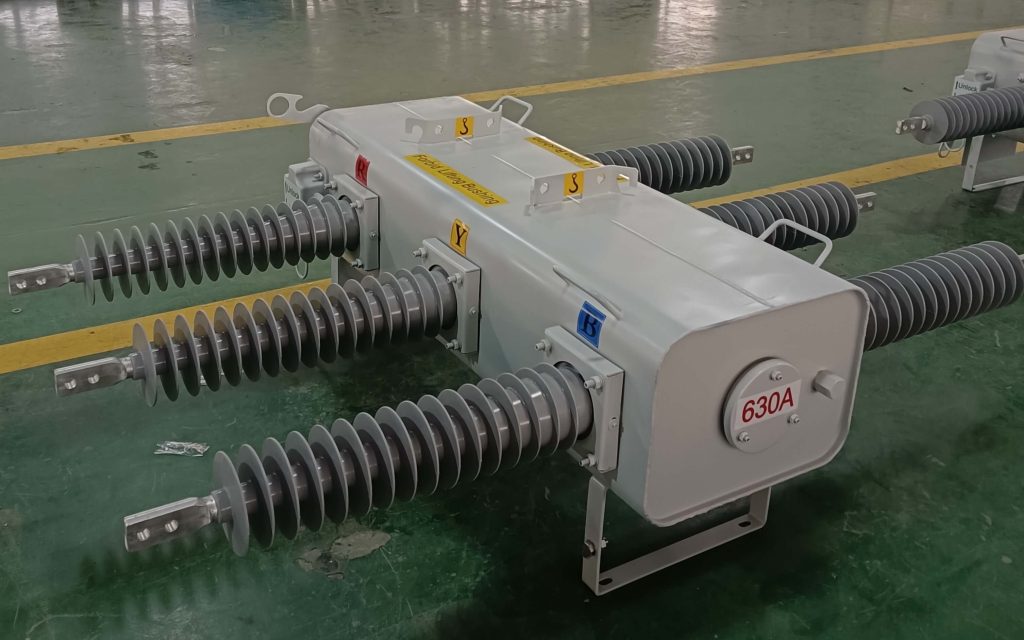
33kV SF6 Load Break Switch
1.1 Working principle
When the switch operates, a spring-energy storage mechanism drives the moving contact. SF6 gas provides both the dielectric insulation between phases/live parts and the arc-extinguishing medium as the contacts part under load. Because SF6 has excellent arc-quenching characteristics and is non-toxic and non-flammable, the interruption is clean and the enclosure stays sealed against weather and pollution.
1.2 Rated parameters (40.5kV class)
| Parameter | Unit | PGS-40.5 |
|---|---|---|
| Rated voltage | kV | 40.5 (applicable to 33/36/40.5kV systems) |
| Rated frequency | Hz | 50/60 |
| Lightning impulse withstand (phase-earth / fracture) | kV | 185 / 215 |
| Power-frequency withstand 1 min (phase-earth / fracture) | kV | 95 / 110 |
| Rated current | A | 630 (400 optional) |
| Rated breaking load current | A | 630 |
| Peak withstand current | kA | 50 |
| Rated short-time making current | kA | 50 |
| Rated short-time withstand current | kA/s | 20 / 4 |
| Rated cable / line charging breaking current | A | 25 / 16 |
| Rated closed-loop breaking current | A | 630 |
| Rated operating pressure (SF6) | MPa | 0.10 (40.5kV) |
| Main-circuit resistance | µΩ | ≤150 |
| Relative gas leakage rate | /year | ≤1% |
| Mechanical endurance | operations | 6000 |
| Rated load-current breaking operations | times | ≥400 |
| Enclosure protection | IP | IP44 / IP54 |
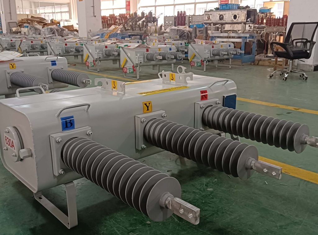
33kV SF6 Load Break Switch
2. Core Technical Advantages of the SF6 Gas-Insulated Design
2.1 SF6 gas insulation with self-extinguishing arc
SF6 is a non-toxic, non-flammable, electronegative gas with outstanding dielectric strength and arc-quenching ability. Sealed inside the GIS enclosure, it protects live parts from rain, salt, dust and pollution — critical for coastal and desert 33kV overhead lines.
2.2 Visible, positive open/closed indication
A color-coded position indicator (green = open, red = closed) is mechanically linked to the main contact drive shaft, so the state shown is the actual contact state — not just a relay signal. A line worker on the ground can confirm isolation at a glance, which is a major safety advantage over sealed-plug or indicator-light-only designs.
2.3 Fast spring-energy operating mechanism (<100 ms)
A miniaturized spring operating mechanism stores energy to guarantee a quick, consistent make/break in less than 100 milliseconds, independent of how fast the operator turns the handle. The mechanism sits inside a sealed box, eliminating the corrosion and icing problems that plague open, exposed mechanisms.
2.4 Rigid, corrosion-proof 304L stainless-steel construction
The enclosure and structural parts use warship-grade 304L stainless steel, rated for a 30-year outdoor life with minimal maintenance — even in high-humidity, coastal or industrial-pollution environments.
2.5 Manual, electric and remote operation
The switch supports manual, electric and remote (FTU) operation. Wired and wireless modems can be mounted in the controller cabinet for SCADA monitoring and control, enabling automated fault-section isolation and fast service restoration on smart grids.
2.6 Zero-pressure insulation capability
Even at zero gauge pressure the design retains a defined insulation level (power-frequency 30 kV, 1 min), giving a safety margin if a slow leak occurs before scheduled maintenance.
3. Typical Applications and Service Boundaries
3.1 Where it fits best
- Radial and loop 33kV overhead distribution networks — for sectioning, load transfer and tie-point switching.
- Automatic fault-section isolation — paired with an FTU, the switch opens to cordon off a faulted span and lets the rest of the feeder re-energize.
- Renewable collection feeders — solar/wind collection points where frequent load-transfer switching is required.
- Industry and utility substations — as a visible, lockable disconnect on the overhead side.
3.2 Service boundaries (what it is NOT for)
Important: A load break switch is a disconnect-class device. It must not be applied as a short-circuit protector. Where automatic fault-current interruption is required, pair it with a circuit breaker, recloser or fuse, or use a switch-fuse combination. The PGS also does not provide earth-fault breaking by itself.
4. Comparison: SF6 vs Vacuum vs Air-Insulated Load Break Switches
| Feature | SF6 insulated (PGS) | Vacuum LBS | Air-insulated (open) |
|---|---|---|---|
| Dielectric medium | SF6 gas (sealed GIS) | Vacuum interrupter | Air / porcelain |
| Pollution / coastal suitability | Excellent (sealed) | Good | Poor (exposed) |
| Visible contact position | Yes (mechanical link) | Limited | Yes (blade) |
| Maintenance need | Very low (sealed) | Low | High (cleaning) |
| Mechanism corrosion risk | Very low (sealed box) | Low | High (open) |
| Remote / FTU control | Yes (standard) | Yes | Rare |
| Service life | ~30 years | ~20–25 years | ~10–15 years |
5. Summary
The 33kV SF6 insulated load break switch combines sealed SF6 gas insulation, a fast spring mechanism, a mechanically linked visible indicator and corrosion-proof 304L stainless steel into a pole-mounted unit built for 30-year outdoor service. It excels at safe load switching, fault-section isolation and remote-controlled network reconfiguration — provided it is applied within its disconnect-class duty and backed by proper protection upstream. Understanding these principles is the first step to selecting and operating it correctly.
Download the full technical datasheet
Get the complete PGS-12/24/40.5 parameter table, dimensions and IEC 60265-1 test summary as a PDF.
Website: www.guoyuanelectric.com/technology/
Email: INTL@guoyuanelectric.com
Frequently Asked Questions
What does ‘SF6 insulated’ mean for a 33 kV load break switch?
It means the switching contacts and interruption chamber are sealed in SF6 gas, using its high dielectric strength for compact, weatherproof insulation instead of air or solid insulation.
How does an SF6 load break switch extinguish the arc?
On opening, the moving contact separates inside the SF6 chamber; the gas quenches the load-breaking arc rapidly, while a dedicated interrupter limits re-strike, enabling safe load current switching.
SF6 insulated vs air-insulated — what is the difference?
SF6-insulated units are sealed, compact and pollution/humidity-independent; air-insulated designs are larger and more climate-sensitive. SF6 suits harsh or space-constrained outdoor sites.
What are the main design features to evaluate?
Seal technology, density monitoring, interlock safety, mechanical endurance class, and the certified short-circuit making capacity of any integrated earthing switch.
Is SF6 regulation a concern for this design?
SF6 is regulated under F-gas frameworks with leak-check and reporting duties, but remains approved for MV switchgear. Specify sealed low-emission designs and confirm local compliance.