
33kV SF6 Load Break Switch: Fault Diagnosis, Troubleshooting and Safe-Use Precautions
When a 33kV SF6 load break switch shows a wrong position indication or loses gas pressure, field crews often cannot pinpoint the cause quickly — risking unsafe operation and delayed restoration.
In this article
- Common Fault Symptoms
- Root Cause Analysis
- Diagnosis and Corrective Steps
- Troubleshooting Comparison Table
- Safe-Use Precautions
- Summary
The PGS-40.5 SF6 load break switch is a sealed, low-maintenance device, but like all outdoor plant it can develop faults from gas leakage, contamination, mechanism wear or improper handling. This article gives field crews a structured way to recognize symptoms, find the cause, and act — plus the handling, storage and inspection rules that prevent most problems.
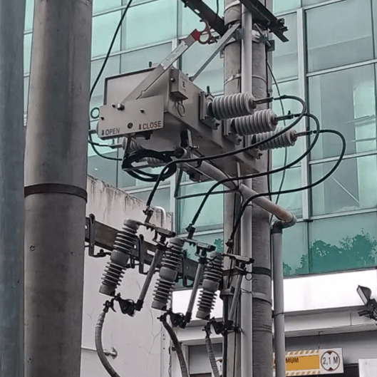
33kV SF6 Load Break Switch
1. Common Fault Symptoms
1.1 Position indicator mismatch
The green (open) / red (closed) indicator disagrees with the known network state, or does not move during operation. Because the indicator is mechanically linked to the contact drive shaft, a mismatch suggests a drive or linkage problem — never assume the contacts are where the SCADA shows them.
1.2 SF6 pressure drop / density alarm
A falling pressure reading (or density alarm where fitted) indicates gas loss. SF6 leakage raises the risk of insulation failure and, at low pressure, loss of the sealed-enclosure safety margin.
1.3 Mechanism will not operate or is sluggish
The handle or motor fails to trip/close, or the operation takes longer than the specified <100 ms. Causes range from a discharged spring to a seized or corroded drive.
1.4 High main-circuit resistance
Loop-resistance measurement above the limit (factory/main-circuit resistance ≤150 µΩ; acceptance <130 µΩ) points to contact burning, looseness or contamination.
1.5 Bushing contamination or damage
Dirt, salt, bird droppings or cracks/chips on the ceramic or rubber bushing reduce creepage and can cause tracking or flashover, especially after long service.
2. Root Cause Analysis
| Symptom | Likely root cause |
|---|---|
| Indicator mismatch | Drive-shaft linkage displacement, indicator flag detachment, or partial mechanism travel |
| Pressure drop | Aged seals/O-rings, loose flange bolts, enclosure puncture, or slow fill loss |
| Sluggish / no operation | Spring not charged, corroded/seized mechanism (if box compromised), motor/control fault, low aux voltage |
| High resistance | Contact erosion from repeated load breaking, loose terminal, contamination |
| Bushing fault | Pollution accumulation, mechanical impact, thermal cycling cracks |
3. Diagnosis and Corrective Steps
3.1 Verify position safely
- Read the mechanical indicator from the ground; do not rely on remote status alone.
- If mismatch, isolate upstream, prove dead, and inspect the drive linkage before further operation.
3.2 Check SF6 pressure and leakage
- Compare the reading with the SF6 pressure–temperature curve (Fig. 8 in the manual) to separate a true leak from normal temperature variation.
- If pressure is below the rated 0.10 MPa (40.5kV) operating value, treat as a leak: locate the source (flange, seal, gauge), and arrange top-up or return-to-workshop service.
- Record the relative gas leakage rate (≤1%/year is the design limit).
3.3 Resistance and mechanism test
- Measure main-circuit resistance; if >130 µΩ at acceptance or trending up, inspect contacts.
- Exercise the mechanism; confirm make/break within 100 ms and that the spring charges and holds.
3.4 Clean and inspect bushings
After a defined service interval, clean the bushing surface to restore creepage. Replace any bushing with cracks or chips. Keep SF6 moisture content within limit (factory ≤150 ppm; in-service ≤300 ppm).
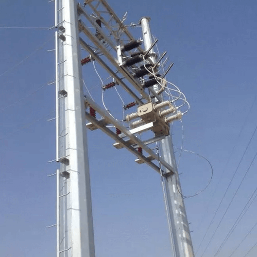
33kV SF6 Load Break Switch
4. Troubleshooting Comparison Table
| Symptom | Cause | Action |
|---|---|---|
| Indicator disagrees with state | Linkage / flag fault | Isolate, prove dead, inspect drive; do not operate until confirmed |
| Pressure below rated value | Seal / flange leak | Check vs temp curve; locate leak; top up or workshop service |
| Won’t trip/close | Spring / control / voltage | Charge spring, check aux voltage & FTU; inspect sealed mechanism box |
| Resistance rising | Contact erosion | Measure trend; plan contact inspection / replacement |
| Bushing tracking/flashover | Pollution / damage | Clean bushing; replace if cracked or chipped |
5. Safe-Use Precautions
5.1 Transport and lifting
Caution: During transport or lifting, no strong vibration, inversion or rolling is allowed. The unit must be packaged before shipment, and the enclosure must not be struck or dropped.
5.2 Acceptance
- Carefully remove and inspect for bumps; pay special attention to porcelain/rubber bushings for chips or cracking.
- Where allowed, measure loop resistance (it shall be <130 µΩ).
- Confirm SF6 filling and sealing; check the pressure gauge (if fitted) reads the rated value at 20°C.
5.3 Storage
Store indoors in a location protected from collision and with good ventilation. Do not leave the switch exposed to weather before installation.
5.4 Operation and gas handling
- Operate only within rated duty — never use it to clear short-circuit fault current.
- Do not open the SF6 enclosure in the field; gas filling and sealing are factory operations.
- Keep the controller cabinet seals intact; forcing the door risks the sealed mechanism and modems.
- Follow the SF6 pressure–temperature curve for correct interpretation of readings.
5.5 Periodic maintenance
- After a running period, clean the bushing surface.
- Monitor SF6 pressure/density and moisture content on schedule.
- Verify mechanical operation and indicator accuracy during planned outages.
6. Summary
Most 33kV SF6 load break switch problems trace to gas leakage, contamination, mechanism wear or mishandling. Field crews should always trust the mechanical position indicator over remote status, interpret pressure against the temperature curve, and keep bushings clean. Respect the transport, storage, gas-handling and duty-limit precautions — they are what make the sealed, 30-year-design unit live up to its low-maintenance promise. When in doubt, isolate, prove dead, and contact the manufacturer before further operation.
Download the troubleshooting checklist (PDF)
A field-ready symptom → cause → action card for crews maintaining PGS-12/24/40.5 switches.
Website: www.guoyuanelectric.com/technology/
Email: INTL@guoyuanelectric.com
Frequently Asked Questions
What are the most common faults on a 33 kV SF6 load break switch?
Typical issues are SF6 density/pressure loss, seal leaks, mechanism sticking, and contact overheating from poor torque. Regular density-monitor and infrared checks catch most problems early.
How do I troubleshoot a low gas-density alarm?
Confirm the density monitor reading, inspect seals and valves for leaks with a leak detector, and never open the enclosure without proper de-rating and PPE. Top-up or repair only per the manufacturer procedure.
What safety precautions apply when working on SF6 switches?
Treat SF6 as an asphyxiant and arc-by-product hazard. Ventilate, use approved PPE, isolate and earth the circuit, and follow lock-out/tag-out. Only trained personnel handle gas recovery.
When should I call the manufacturer service instead of field-fixing?
For internal arc damage, repeated density loss, or any fault involving the interrupter chamber, return to authorised service — field intervention risks seal integrity and safety.
How can I extend service life and avoid faults?
Scheduled density inspections, torque verification of connections, and keeping the mechanism clean and lubricated per the maintenance manual typically deliver 20+ years of reliable operation.